The project that taught me to think in systems
In 2016, for my Year 12 VCE Systems Engineering project, I designed and built the Balance Board: a pressure-sensing platform intended to explore how changes in standing weight distribution could be made visible.
The original brief began with balance impairment following conditions such as stroke and acquired brain injury. I wanted to investigate whether a compact system could measure pressure beneath each foot and turn it into information that might help a practitioner observe change over time.
This was an ambitious school prototype, not a medical device or clinical study. Its achievement was proving the complete engineering idea: sense force, condition and convert eight analogue signals, interpret them in software, and package everything into something a person could stand on.
Research before construction
I began by examining how existing systems approached different parts of the problem.
The Xbox Kinect could observe whole-body movement but did not directly measure pressure beneath the feet. The Wii Balance Board showed how four load sensors could turn weight distribution into interactive feedback. I also bought and disassembled a bathroom scale to understand how its strain gauges, rubber feet, calibration behaviour, and compact electronics worked together.
The rehabilitation research I read suggested that pressure-based feedback was worth exploring. It did not validate my design, but it helped establish useful requirements: keep the platform portable, low-profile, stable, repairable, practical to store, and capable of presenting its readings in real time.
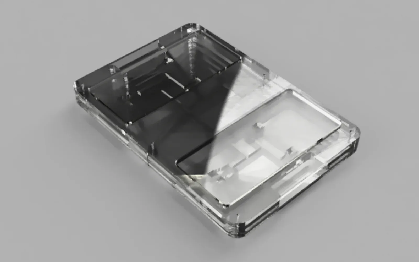
I compared three physical layouts. The selected option removed an integrated screen and used an external HDMI display instead. That kept the board smaller and lighter while allowing the output to appear on a screen appropriate to the setting. Rounded corners, carrying handles, rubber feet, and a bolted layered enclosure addressed handling, stability, and future repair.
2016 / DESIGN_BRIEF
- 8
- Force-sensing inputsFour pressure points beneath each foot platform.
- 20–140 kg
- Intended design rangeA design target from the folio, not a certified load rating.
- 10-bit
- Analogue conversionAn MCP3008 converted eight conditioned signals for the Raspberry Pi.
- $453.31
- Recorded build costThe one-off bill of materials documented in the 2016 folio.
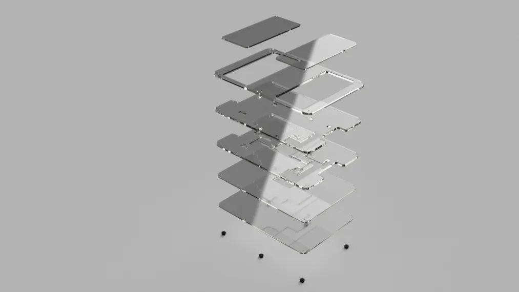
The layered construction separated the foot platforms, sensing pockets, wire paths, Raspberry Pi enclosure, and serviceable base.
Prototype before committing to acrylic
The enclosure started as a set of Fusion 360 sketches and became two deliberately inexpensive prototypes.
Version one used foam board so I could check the overall footprint, component clearances, and laser-cut geometry quickly. Version two used MDF in the same 5 mm and 10 mm thicknesses planned for the final acrylic. That made the height, foot-platform travel, sensor pockets, wire channels, handles, fastener positions, and Raspberry Pi access testable before I committed to the expensive material.
The prototypes changed the design in practical ways. Square edges became rounded, the Raspberry Pi rotated so power and HDMI remained accessible, duplicated wire channels were removed, and the Pi was mounted rather than left loose inside the enclosure. Bolts replaced permanent adhesive so the finished board could be opened without destroying it.
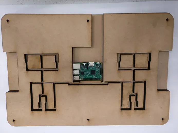
The full-thickness MDF prototype tested the physical stack before the final acrylic was cut.
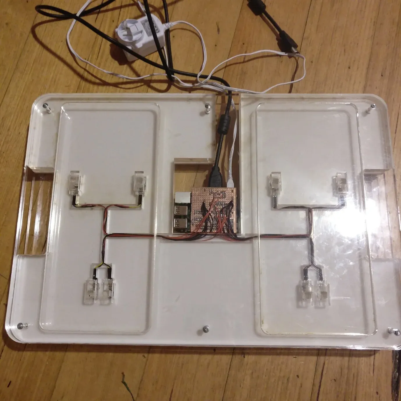
The final acrylic assembly brought the sensing layers, wiring, custom interface, and Raspberry Pi into one serviceable enclosure.
When the preferred sensor failed
I compared strain gauges, force-sensitive resistors, and Quantum Tunnelling Composite, or QTC. An early decision matrix favoured QTC because of its small footprint, apparent repeatability, and low component cost.
The physical test told a different story.
I designed and milled small copper carrier boards for the QTC pills, connected them through an MCP3008 analogue-to-digital converter, and loaded the prototype. The response stopped changing beyond a relatively small force. Further investigation identified a maximum force around 100 newtons—roughly 10 kilograms—far below the prototype’s intended design range.
The comparison had been built on an incorrect assumption, so I changed the design. I returned to force-sensitive resistors, which I had already tested with operational-amplifier circuits. The switch required new sensor pockets and the removal of channels designed specifically for QTC, but the CAD model and layered construction kept the change contained.
That pivot remains one of the most important parts of the project. The test invalidated the preferred component, and the evidence mattered more than defending the original choice.
One system, from force to feedback
The finished prototype brought mechanical design, analogue electronics, embedded computing, and software into one chain:
force → eight FSR sensors → MCP6004 operational amplifiers → MCP3008 ADC → SPI → Raspberry Pi 3 → Python visualisation
Four sensors sat beneath each foot platform. Small acrylic pucks focused pressure onto them, while the layered chassis routed their wiring into the central electronics bay.
The Raspberry Pi 3 was selected after comparisons with the BeagleBone Black, Arduino Uno, and Intel Edison. It provided the processing, networking, and HDMI output needed in one board. Because it had no analogue inputs, the MCP3008 converted the eight conditioned sensor signals into 10-bit digital readings and sent them to the Pi over SPI.
I built a custom stripboard interface joining the ADC, two quad operational amplifiers, and the sensor connections. Python read the channels and drove graphs representing overall, horizontal, and vertical pressure distribution on an external display.
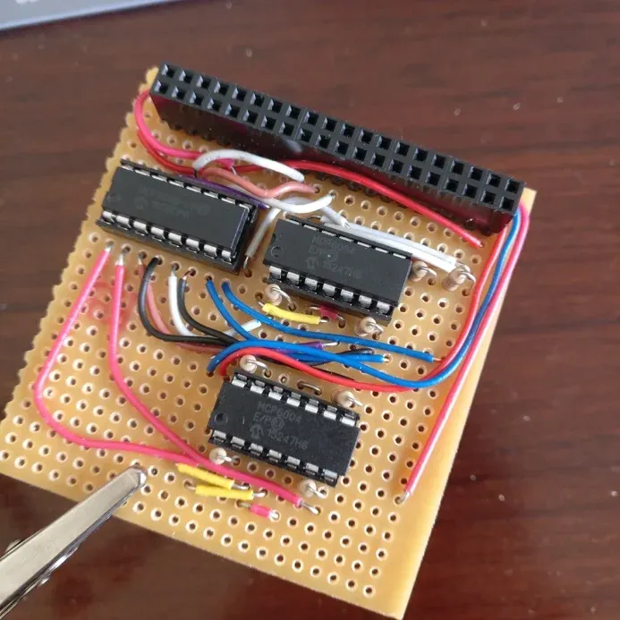
The custom interface amplified eight sensor signals, converted them to digital readings, and connected directly to the Raspberry Pi.
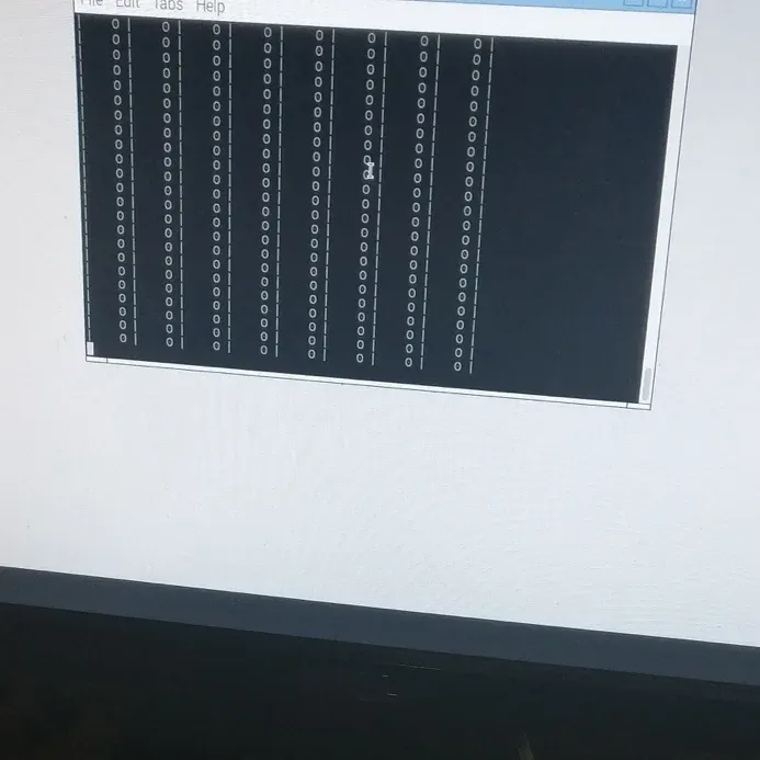
A dedicated diagnostic program exposed every input channel before the readings were transformed into graphs.
What the diagnostics showed
I separated testing into board, sensor, and program diagnostics.
The Raspberry Pi booted successfully, accepted its keyboard and mouse, supported SSH and VNC access, and completed a power cycle without an error. With no load, all eight sensor channels returned zero.
During a centred standing test, the channels read 90, 91, 92, 92, 90, 91, 93, 90—a spread of three ADC counts. Moving weight to the left and right changed the corresponding channels, while stepping off returned them to zero. The visualisation reacted to the same changes and stopped when the applied force fell below its threshold.
These were functional engineering diagnostics, not clinical validation. They showed that the input-to-output loop worked; they did not establish medical accuracy, safety, repeatability across users, or any rehabilitation outcome.
Where the prototype stopped
The folio was honest about what another version would need.
Acrylic was accessible and precise to fabricate, but could crack if repeatedly dropped. The hand-built stripboard interface left wiring that would be inappropriate to service while powered. External power and HDMI cables introduced practical trade-offs, and the one-off parts cost reached $453.31.
Most importantly, I tested the prototype myself rather than against a calibrated reference instrument, with clinicians, or with a participant group. Its 20–140 kg design target was a design criterion, not a certified load rating. A credible next iteration would need calibrated sensing, repeatability testing, a professionally fabricated PCB, a tougher enclosure, formal safety work, and appropriately governed user evaluation.
Why I am still proud of it
The Balance Board is not here because it was ready for a clinic. It is here because, as a Year 12 project, it was an unusually complete expression of systems engineering.
I moved from a human problem into literature and product research, dismantled an existing device, compared architectures, modelled and fabricated multiple prototypes, designed analogue electronics, wrote software, diagnosed the completed system, and documented where it fell short.
The most valuable lesson was not that every early decision was right. It was learning to build in a way that made being wrong survivable.
That combination—caring about the problem, following evidence across disciplines, and changing course when the prototype disagrees—is still how I want to make things, including the plant monitor that is taking me back into electronics.